 Create a helix with a law controlled radius
 Create a helix with a law controlled radius
This example shows how to create a helix with a law controlled radius.
Choose Insert→Curve→Helix.
In the Helix dialog box, the Number of Turns box, type a value for the number of turns you want the helix to make about its axis.
For this example, a value of 3 is entered.
Note:
The value can be less than 1 to make a partial turn (such as 0.5), but it must be greater than 0 (zero).
In the Pitch box, type a value to define the separation distance between each turn.
For this example, a value of 1 is entered.
In the Radius Method group, click the Use Law option.
In the Law Function dialog box, click the Linear ![]() option.
option.
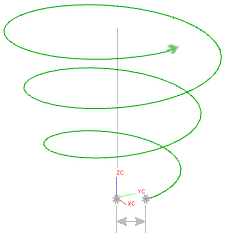
In the Law Controlled dialog box, in the Start Value box, type a value for the distance from the start point of the helix to the base point on the helical axis.
For this example, a value of 1 is entered.

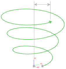
In the End Value box, type a value for the distance from the end point of the helix to the helical axis.
For this example, a value of 2 is entered.

Click OK.
.
In the Helix dialog box, in the Turn Direction group, click the Right Hand option for a helix that turns counterclockwise, or the Left Hand option for a helix that turns clockwise.
For this example, the Right Hand option is selected.
Click OK or Apply to create the helix.
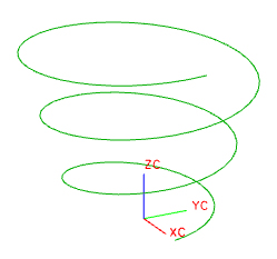
The helix is created in the default ZC direction on the WCS.

|
Number of Turns: |
3 |
|
Pitch: |
1 |
|
Radius Method: |
Use Law = Linear |
|
Start Value: 1 |
|
|
End Value: 2 |
|
|
Turn Direction: |
Right Hand |