 Create a helix with a fixed radius
 Create a helix with a fixed radius
This example shows how to create a helix with a fixed radius by defining its direction and location.
Choose Insert→Curve→Helix.
In the Helix dialog box, in the Number of Turns box, type a value for the number of turns you want the helix to make about its axis.
For this example, a value of 3 is entered.
Note:
The value can be less than 1 to make a partial turn (such as 0.5), but it must be greater than 0 (zero).
In the Pitch box, type a value to define the separation distance between each turn.
For this example, a value of 1 is entered.
In the Radius box, type a value for the constant radius of the helix.
For this example, a value of 2 is entered.
In the Turn Direction group, click the Right Hand option for a helix that turns counterclockwise, or the Left Hand option for a helix that turns clockwise.
For this example, the Right Hand option is selected.
Click Define Orientation.
The Specify the orientation dialog box appears to let you select the Z-Axis for the helix.
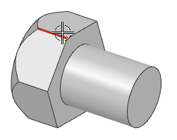
In the graphics window, select an existing edge that you want to use to define the orientation of the helical axis.
For this example, the red highlighted edge is selected.
The end of the line that is selected determines the direction.

Note:
If you do not select the Define Orientation option, NX uses the ZC-Axis and the WCS for the helix base point
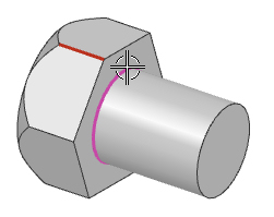
In the Point dialog box, specify the base point of the helical axis (around which the helix will turn).
For this example, the center of the highlighted arc is selected for the base point.

Click OK, to close the Point dialog box.
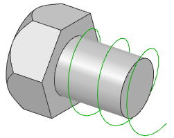
Click OK or Apply to create the helix.
The helix is created with its base point on the specified arc center point.

|
Number of Turns: |
3 |
|
Pitch: |
1 |
|
Radius Method: |
Enter Radius = 2 |
|
Turn Direction: |
Right Hand |