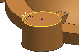
This example shows how to create a counterbored Screw Clearance Hole feature at the center of circular edge.
On the Feature toolbar, click Hole ![]() or choose Insert→Design Feature→Hole.
or choose Insert→Design Feature→Hole.
In the Hole dialog box, from the Type list, select Screw Clearance Hole.
On the Selection bar, make sure that Arc Center ![]() is selected.
is selected.
In the graphics window, click the edge of the cone to select the arc center.

In the Form and Dimensions group, enter values for Form, Screw Type, Screw Size, and Fit.
For this example, the following are selected:
Form list→Counterbored.
Screw Type list→Socket Head, 4762.
Screw Size list→M10.
Fit list→Normal (H13).
|
|
Click OK to create the Screw Clearance Hole feature.
|
|
|
|
|
Note:
For the dimensions of other Screw Clearance Holes, see: