
Contents:
A) Mechanical injecion mold Slide Design Standards
B) Hydraulic injecion mold Slide Design Standards
B) Injection Mold Lifter Standard
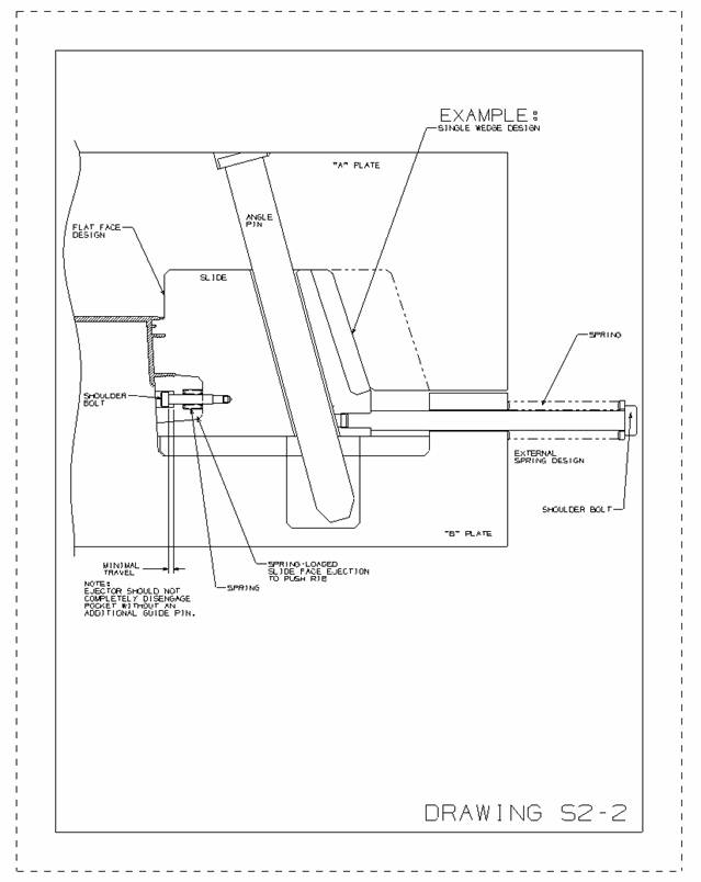
A) Mechanical injecion mold Slide Design Standards (refer to drawing S2-1 & S2-2):
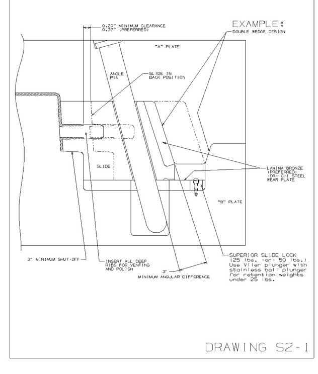
 1) All shut-off surfaces must have a minimum of three degrees draft in direction of slide travel. Any
shut-off angle less than three degrees must have written customer approval.
1) All shut-off surfaces must have a minimum of three degrees draft in direction of slide travel. Any
shut-off angle less than three degrees must have written customer approval.
2) Two angle pins will be required on any slide design that exceeds seven inches in length. Consider a center Slide Guide
for all long slides.
3) There must be a minimum of three degrees difference between the angle pin and back wedge.
4) The back wedge surface of the slide must have a lamina bronze (preferred) or 0-1 steel wear plate to allow for adjustment
and for maintenance of wear surfaces.
5) The back wedge must be designed to resist injection pressure by backing up the entire molding surface. A double-wedge
design must be considered for all large molding surfaces.
6) There must be a minimum of 0.20” ( 0.37” preferred ) clearance between slide detail and the molded part
when slide is in the back position.
7) There can be no ejection under the slide detail without written Customer approval. If the customer accepts
ejection under the slide detail, limit switches must register both forward and back movement of the ejector system.
8) Slides that mold large areas of part shape must have sufficient cooling. Consider Mold Max sub-inserts for difficult
to cool details.
9) All deep rib details must be sub-inserted for venting.
10) Consider spring-loaded slide face ejection for all long wall or deep rib details.
11) Superior slide locks of sufficient weight retention can be used for slide retention in the back position.
12) Slides with flat faces that engage the cavity in direction of slide travel must be designed with face-loaded or
external springs to prevent gaulding. In designs with slides on the “TOP” of mold, slide-face-mounted
or external spring designs are to be used instead of Superior slide locks.
13) There must be a minimum of 6-points hardness (RcC) between the Gib material and the slide material.
14) The length of the slide foot must be 50% of the overall height of the slide.
B) Hydraulic injecion mold Slide Design Standards
1) All mechanical slide design standards relative to shut-off, molding surfaces, and cooling will apply to the Hydraulic
Slide designs.
2) Parker series 2-H hydraulic cylinders will be used. The selection of cylinder bore size and cylinder mount style will be determined by slide size, amount of molding surface (injection pressure), and sequence of hydraulic pull and set. DO NOT USE PARKER MOUNTING STYLE “J” or “JB” DUE TO THE DECREASE IN PRESSURE RATING.
3) In cases where the slide rod is screwed directly into the slide body, make sure wrench flats can be easily accessed for assembly,
or use a double-rod-end cylinder.
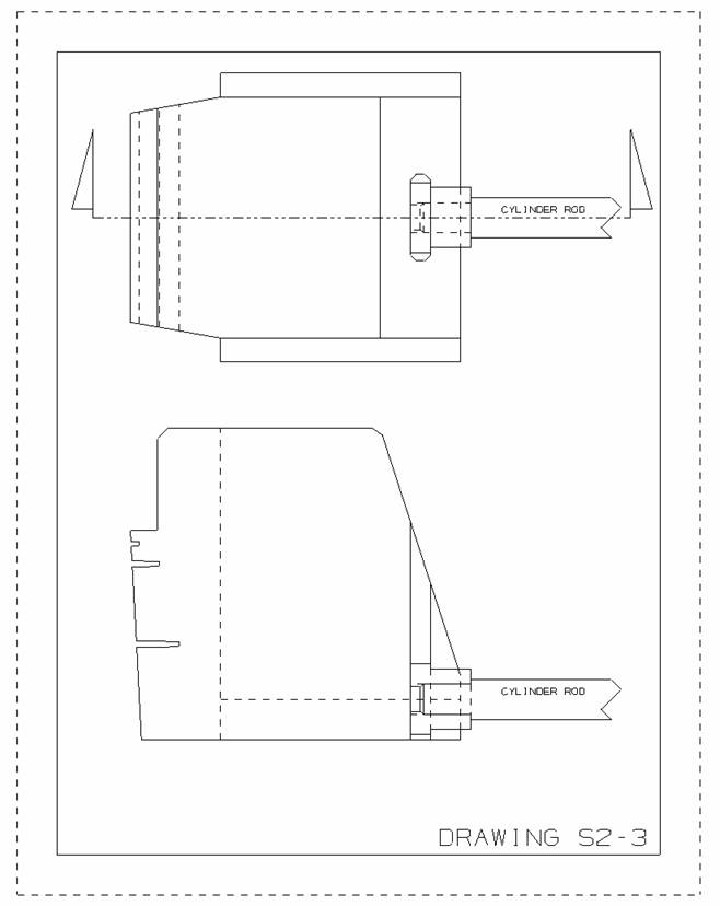
4) “T” style couplings can be used to secure the cylinder rod end to the slide. (Refer to drawing S2-3)
 5) Unless otherwise specified by the Customer, use Parker “EPS” style solid-state proximity switches.
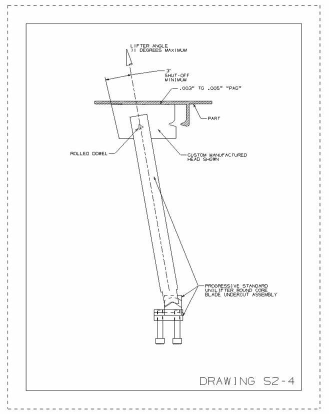
C) injecion mold lifter Design Standards (refer to drawing S2-4):
1) Whenever possible use the Progressive Standard Unilifter Round Core Blade Undercut Release System with a standard Progressive head detail
or a custom manufactured head detail retained to the rod portion of the assembly with a rolled dowel. All Progressive Application
Guidelines must be adhered to.
2) The head design of the lifter must have a minimum of 3-degrees shut-off.
3) Maximum angle acceptable for lifter travel is 11 degrees without special design considerations.
4) Provide a .003” to .005” pad on top of the lifter to prevent part “drag”.
5) Most parts will have a tendency to “ride” with the lifters (remaining on the detail formed by the lifters),
which will not let the parts fall free. In situations where there are no details/side walls to retain the parts, consider
extending ejector pins into the wall section and/or add “gripper” details to the face of the ejectors
(REQUIRES THAT EJECTOR PINS BE KEYED). Molded guide posts can also be considered, but must be approved by the Customer.

Injection Mold slide lifter standards
Injection Mold runner standards
Injection Mold cooling standards
Injection Mold venting standards
Injection Mold Ejector System standards standards
Injection Mold component standards
Injection Mold Hydraulic and Pneumatic standards
Injection Mold Design Check standards
Injection Mold Steel Grades standards
Injection Mold inspection standards