Definition
A weld or meld line on plastic parts can cause structural problems and/or be visibly unacceptable.
Difference between weld and meld lines
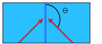
The difference between a weld and meld line is simply determined by the angle at which the converging flow fronts meet.
In the above diagram, the converging flow fronts (indicated by red arrows) meet. If the angle, , is greater than 135 agree meld line will form. If is less than 135?a weld line will form.
Weld Lines
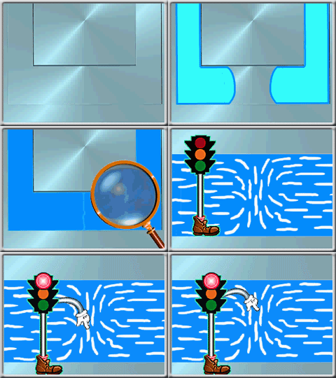
When a weld line forms, the thin frozen layers at the front of each flow path meet, melt, and then freeze again with the rest of
the plastic. The orientation of the plastic at the weld is therefore perpendicular to the flow path. The following animation shows plastic filling a cavity. The weld
line occurs where two flow fronts meet, and the polymer molecules are misaligned.
It is the sharp difference in molecular orientation at the weld which causes the significant decrease in strength at this point.
Meld Lines
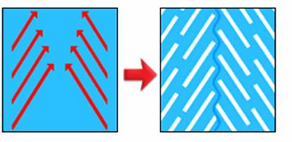
A meld line occurs when two flow fronts blend together at an oblique angle. The orientation of the plastic molecules is therefore
more uniform than the orientation after a weld line has formed. The following diagram shows the length of a part where a meld line forms.
The red arrows show the direction of plastic flow. The white lines represent the orientation of the polymer molecules after the
meld line has formed.
Meld lines are normally stronger than weld lines and are often much less visible.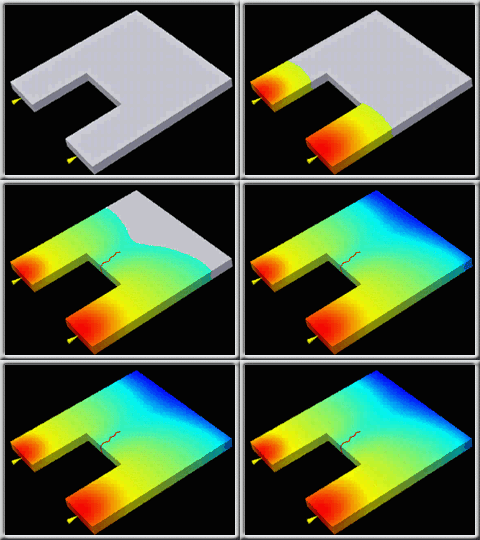
Note: The term weld line is often used to mean both weld and meld lines.
Weld and meld lines on a plastic part can cause structural problems and be visually unacceptable. (A line, notch and/or color change can appear.)
Therefore weld and meld lines should be avoided if possible (when the cavity has unbalanced flow paths unnecessary weld and meld lines can occur).
If it is not possible to remove a weld/meld line, it should be positioned in the least sensitive area possible. Avoid weld lines
in areas which need strength, or which need to appear smooth. This can be done by changing the polymer injection location or altering wall thicknesses to set up a
different fill time. In a different fill time, flow fronts may meet at a different location and therefore the weld/meld line will move.
Moving:
Alter gate positions
Change part thickness
Improving the quality:
Increase melt & mold temperature
This will allow the flow fronts to weld to each other better.
Increase ram speed
Optimize runner system design
Reduce runner dimensions while maintaining the same flow rate to make use of frictional heating.
Note: The processing conditions help to determine the quality of the weld or meld line that has formed. A good weld occurs when the melt temperature is no lower than 20°C below the injection temperature.
Solving one problem can often introduce other problems to the injection molding process. Each option hence requires consideration of all relevant aspects of the mold design specification.
Injection Molding air trap issue and solution
Injection Molding brittleness issue and solution
Injection Molding burn issue and solution
Injection Molding crack issue and solution
Injection Molding delamination issue and solution
Injection Molding dimensional variation issue and solution
Injection Molding discoloration issue and solution
Injection Molding excessive part weight issue and solution
Injection Molding fish eye issue and solution
Injection Molding flash issue and solution
Injection Molding follow line issue and solution
Injection Molding hesitation issue and solution
Injection Molding high volumetric shrinkage issue and solution
Injection Molding jetting issue and solution
Injection Molding overpacking issue and solution
Injection Molding racetrack effect issue and solution
Injection Molding short shot issue and solution
Injection Molding sink mark and void issue and solution
Injection Molding unbalanced flow issue and solution
Injection Molding underflow issue and solution
Injection Molding warpage issue and solution
Injection Molding weld and meld line issue and solution


