
D-M-E Has a Standard Assembly for Most Any Molding or Die Casting Application
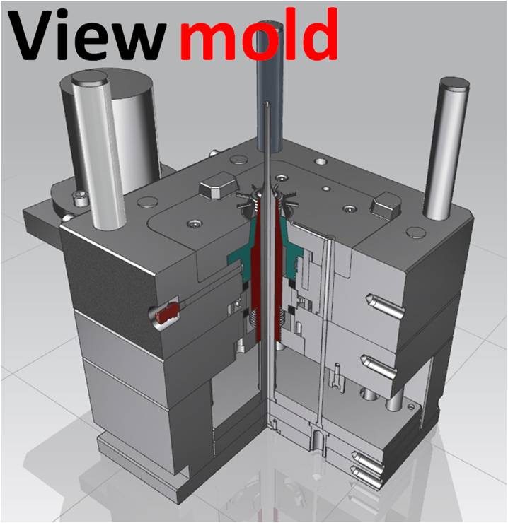
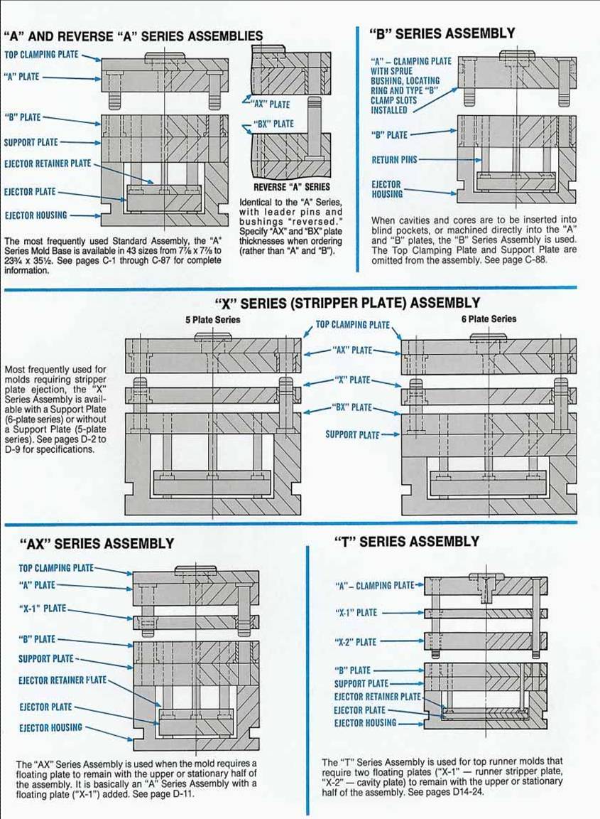
DME standard A series mold bases
DME standard B series mold bases
DME standard X series mold bases
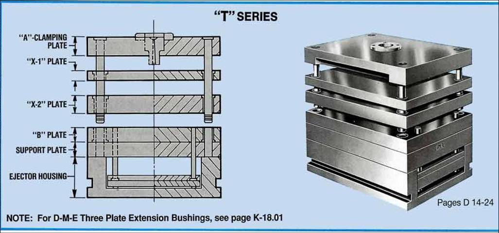
DME standard T series mold bases
DME standard Small-Shuttle Mold Bases
DME Euro-Series Mold Bases
D-M-E Mold Base and Plate Services
D-M-E Custom-Configured Mold Bases
If you need injection mold design services as DME standard, please contact our company.
Here are seven reasons why you should "Go Standard" with D-M-E Mold Base Assemblies and Components.
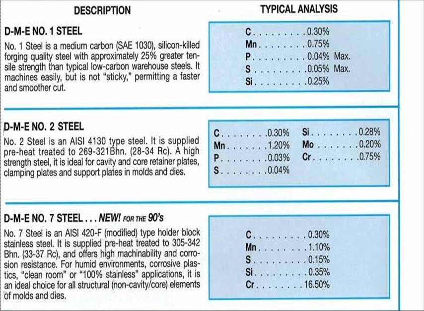
1. They are made of high quality, pre-finished mold and die steels that give you more for your money; more metallurgical consistency; more cleanliness In cavity steels; more reliability.
2. Assemblies, plates and components are pre-engineered to give you the economic and technical benefits of Interchangeability.
3. They are manufactured with the most advanced, precision equipment - and quality control tested to give you reliable performance.
4. They give designers more freedom and flexibility - more time to devote to the truly creative aspects of mold, die, and product design.
5. They give mold and die makers more time to concentrate on cavities and cores - thus Increasing productivity as much as 403/8.
6. They give molders and die casters more quality parts per hour, more profitability - with production proven construction that outlasts the longest runs.
7. They are readily available as you need them. The more popular assemblies are always in stock for same-day service. Our nationwide network of Service
Centers means you have the products and the people near you to help you save time, money and inventory costs.

DESCRIPTION
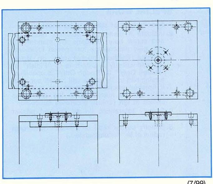
They are reproduced full scale so the designer can lay out the cavities and other required parts without the necessity of drawing such details as screws, dowels, leader pins. etc. This eliminates the chance for error in locating the majority of mold base details. The efficient mold designer should have a set of D-M-E Master Layouts on hand covering all sizes he is likely to use.
A Master Layout is available for each of the A" Series Mold base sizes; i.e., 108A, 1012, etc. up to 2435A, except for 812A and 45R.
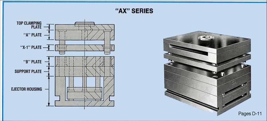
When master layouts for "AX" and "T"Senes mold bases are required, order comparable size A" Series master layout and include floating "X" plates in your design. A" Series master layouts can also be used for "X" series mold bases by noting that leader pins and bushings shown in the upper plan views are reversed.
Master Layouts are also available for most Custom Designed and Compression bases Shown in Sections B and E of this catalog. For die casting, layouts are also available for Unit Dies and Replacement Units Shown in Section F.
Layouts can be ordered in two styles -- black lines on white paper or sepia lines on transparent paper. See price list for full details.
When ordedng, please specIfy: 1 QuantIty 2.Type 3.Mold Base size (e.g.5.-Black on White --1215A Mold Base)
For Example: 1016A-13-37 is the catalog number for a 9 x 16" "A" Series Mold Base with "A" plate 13/8 and "B" plate 3 thick.
All "X" Series Mold Bases
The catalog numbers for the Stripper Plate Series Bases combine the NOMINAL Size (width and length), the letter "X" for Stripper Plate the numeral 5 or 6 (plate series) and the "AX" plate thickness.
Since the "X" plate thickness is constant at or 1 and the "BX" plate thickness is constant at 1-3/8, 1 or 2-3/8, depending on the mold base nominal size and number of plates In the assembly, these Ihick Mol nesses are not represented in the catalog number.
For Example: 1818X-5-13 is the catalog number for a 17 x 18", 5-plate "X" Series Mold Base with a 1 thick "AX" plate. (In this case, the "X" plate is 1 thick. and the "BX" plate Is 2-3/8 thick).
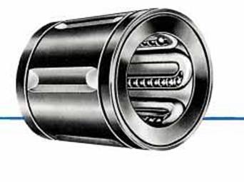
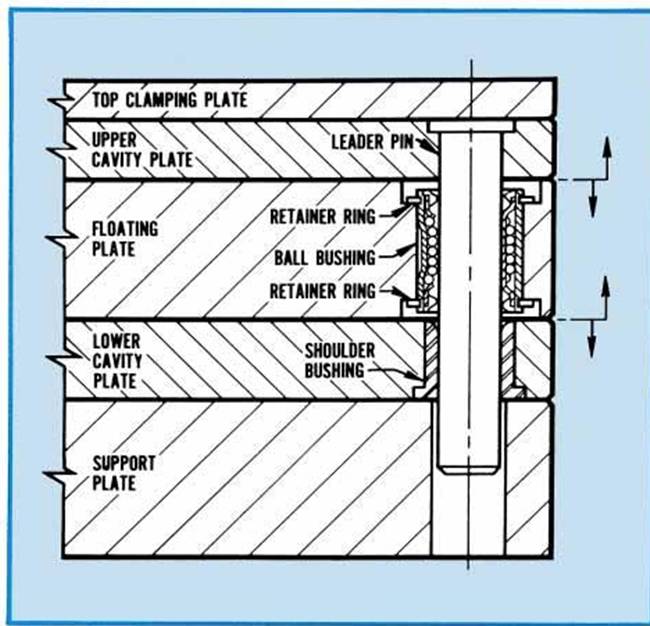
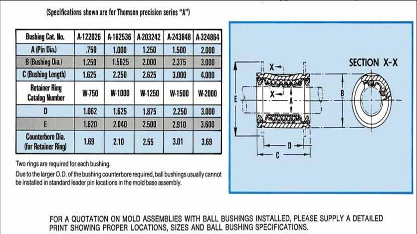
The illustration (Left) shows a typical installation of the "lineal" type ball bushing - the most basic and least expensive type of low-friction, ball bearing bushing. The ball bearings in the lineal- type bushing are retained in the hollow walls of the bushing itself. In use, the movement of the ball bearings is continuous along a straight line on the surface of the leader pin. Note from the chart below that only one standard length of ball bushing is available for each pin diameter. This minimizes the number of plate thicknesses which can accommodate "lineal" type ball bushings. Also note that "grooveless" leader pins must be installed to prevent interference with the ball bearings.
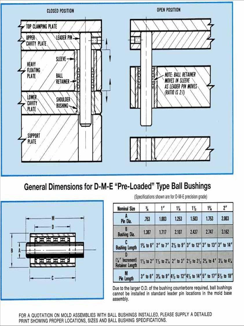
The illustrations (below) show a typical application of the "pre-loadect" type of ball bushing. With this type of ball bushing, a separate ball retainer moves between the leader pin and the sleeve. This prevents lateral movement under severe conditions and assures uniform wear around the circumference of the leader pin. The ratio of movement between the leader pin and the ball retainer is 2:1 (i.e. for every 1" of leader pin travel, the ball retainer moves 1/2"). Installation of these ball bushings requires that the holes for the leader pins, sleeves and shoulder bushings must be jig bored for accurate alignment. It is also important to note that all the bail bearing retainers in an assembly must be "timed" for uniform movement. Wherever possible, the floating plate thickness should not be less than the minimum standard sleeve length.
For Example: 1212AX-13-37 is the catalog number for an ll 12 "Ax" Series Mold Base with a 13/8 thick "A" plate and 37 thick "B" plate. The "X..l" plate thickness (e.g. is then specified when ordering, All "T" Series Mold Bases
D-M-E Standard "T" Series Mold Bases are available in 42 standard sizes, from 7/8 x 77/s to 23 x 35 They are used for top runner molds that require two floating plates ("X-1" - runner stripper plate, "X-2" - cavity plate) to remain with the upper or stationary half of the assembly.
The catalog numbers for the "T" Series Mold Bases combine the NOMINAL Size (width and length), the letter "T" and the thickness of the "X-2" and "B" plates.
Since the thickness of the "A"-Clamping plate is constant at or 23/8 and the "X-1" plate thickness is Constant at or 13/8, dependIng on the nominal size of the mold base, these thicknesses are not represented In the catalog number.
For Example: 1012T-23-17 is the catalog number for a 9 x 11 "T" Series Mold Base with a 2-3/8 thick "X-2" plate and 1 thIck "B" plate. (In this case, the "A"-Clamp in plate is 1 thick and the "X-1" plate is thick),
Since Cavity Retainer Sets are made up solely of an "A" and "B" plate, the catalog numbers combine the NOMINAL Size, and the "A" and "B" plate thick- nesses. (The absence of the letter "A��, "B", "AX", or "T" distinguish those numbers from the catalog num Fo bers of Standard Mold Bases).
Example: 1215-33-47 is an 11 x 15" Cavity Re- tairier Set with "A" plate 3 and "B" plate 4 thick.
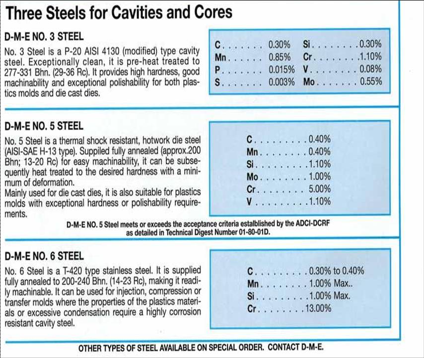
#1, #2, #3 Steel from 7 / 8 " Thick to 5 7 / 8 " Thick
The same principle used for numbering Cavity Retamer Sets is applied to Standard Mold Plates; however, only one plate thickness is required. (Since the catalog numbers for retainer sets will always indicate
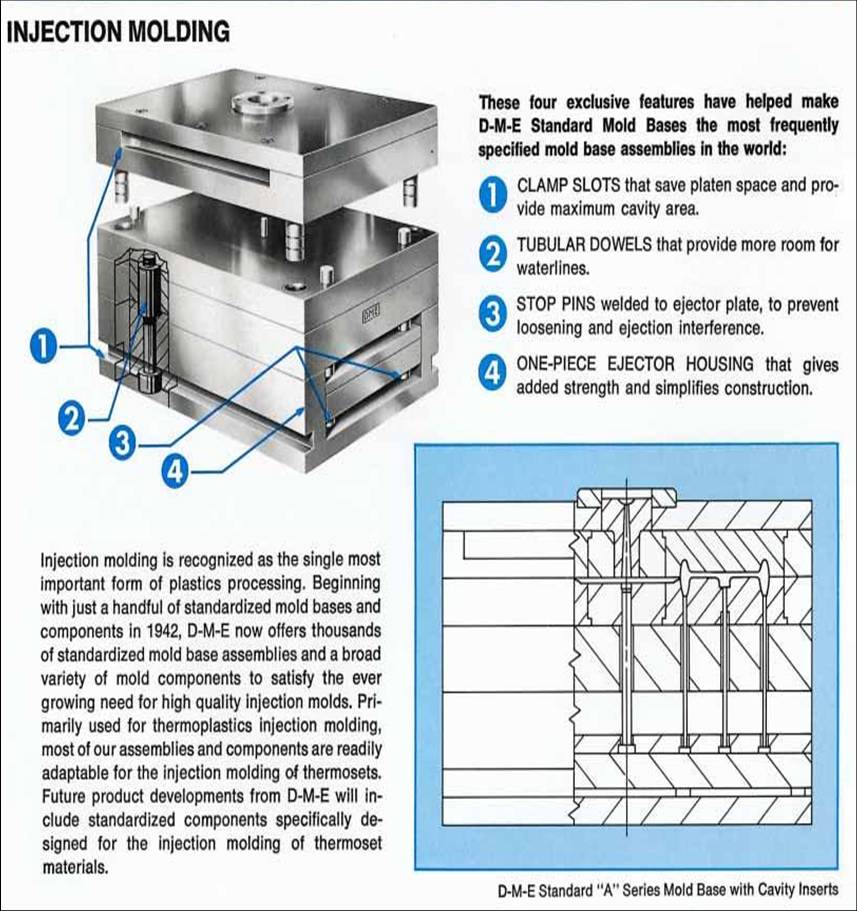
1-Piece or 3-Piece Housing (Standard D-M-E Rails)
Relocate Return Pins
Relocate Assembly Screws (top and/or bottom)
Relocate Assembly Screws in Ejector Set
Relocate Leader Pins and Bushings
Relocate Center Holes
Relocate Stop Pins in Ejector Bar
Sprue Puller Pin of Your Choice
Machining for All D-M-E Sprue Bushings and Clamp Slots
Machining for Most Locating Rings
Includes
All D-M-E Standard Mold Bases
#1, #2, #3 Steel ( 7/8"-5 7/8" thick) and #7 Steel ( 7/8"-2 7/8" thick)
All Items Listed Under Charge Features-Plus:
-Machine for and Install Guided Ejection-2 or 4 Places
-Machine for and Install Support Pillars
-Machine for and Install Additional Stop Pins
-Machine Press Knock-Out in Bottom Clamp Plate (Tap in Ejector Bar if Required)
-Machine Pry Bar Slots
-Machine Leader Pin Vent Slots in Rails
-Machine for Spring Pockets
-Drill and Tap Eyebolt Holes
-Drill and Tap Safety Strap Holes (Locations1/32")
-Machine for and Install Extra Assembly Screws in Top and/or Bottom
-Machine for and Install Extra Assembly Screws in Ejector Assembly
-Machine for and Install Added Return Pins
-Rough Mill/Bore a Cavity and Core
Pocket; Blind or Through (Note:1/2" Minimum Radius Required)
Includes All Features Specified in 5 Working Days Ship PLUS:
-Machine for D-M-E 3-plate Extension Bushings (D-M-E Catalog page K18.1)
-Drill and Tap Horizontal Water Lines
-Drill Water Pipe Clearance Holes
-Drill Vertical Water Lines
-Machine for D-M-E Angle Pin Inserts (D-M-E Catalog page K18.4)
-Finish Mill/Bore a Cavity and Core Pocket; Blind or Through (Note:1/2" Minimum Radius Required)
Includes All Features Specified in 7 Working Days Ship PLUS:
-Machine for D-M-E Parting Line Interlocks (D-M-E Catalog pages K22.6 -K25)
-Provide Special Thickness Plates